| |
This week's assignment was to make something Big:
Test runout, alignment, speeds, feeds, and toolpaths for ShopBot machine.
CNC stands for Computer numeric control which translate programs consisting of specific numbers and letters to move the spindle (or workpiece) to various locations and depths. Most CNC Mills require placing your workpiece on or in them and must be at least as big as your workpiece, but new 3 axis machines are being produced that you can put on your workpiece, and can be much smaller.
To start with something big, I have decided to use the ShopBot CNC router machine. The CNC router is a machine that uses a cutting bit that rotates at a very high speed to remove material from a part. The machine reads a pre‐programed computer file telling it where and how to cut. A cutting bit is rotated at a very high RPM by a spindle motor, which can move the bit up and down. This mechanism is moved left, right, front, and back by a cross arm. The machine is therefore known as a three‐axis router because it can move on the XY & Z axis. The machine can do two dimensional cutouts and etching, as well as three‐dimensional relief work. You can cut MDF, plywood, solid wood, foam, plastics and soft metals (like aluminum) using this machine. The thickness of the material should always be measured using a Vernier caliper.
Before going to start the design, be sure to leave at least an inch (2-3cm) around the perimeter of the material. You need to be very careful that, you need to screw the material to the bed of the ShopBot and you do not want the cutter to hit the screws. The free space between the pieces will depend on the diameter of the cutter you use as well.
Designing & Prototyping
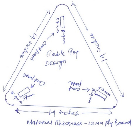
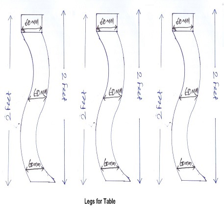
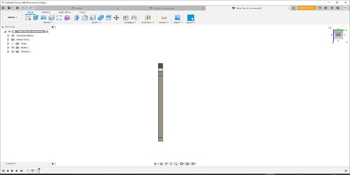
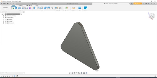
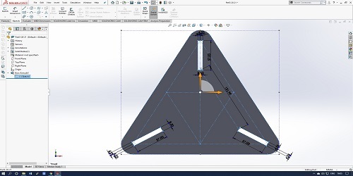
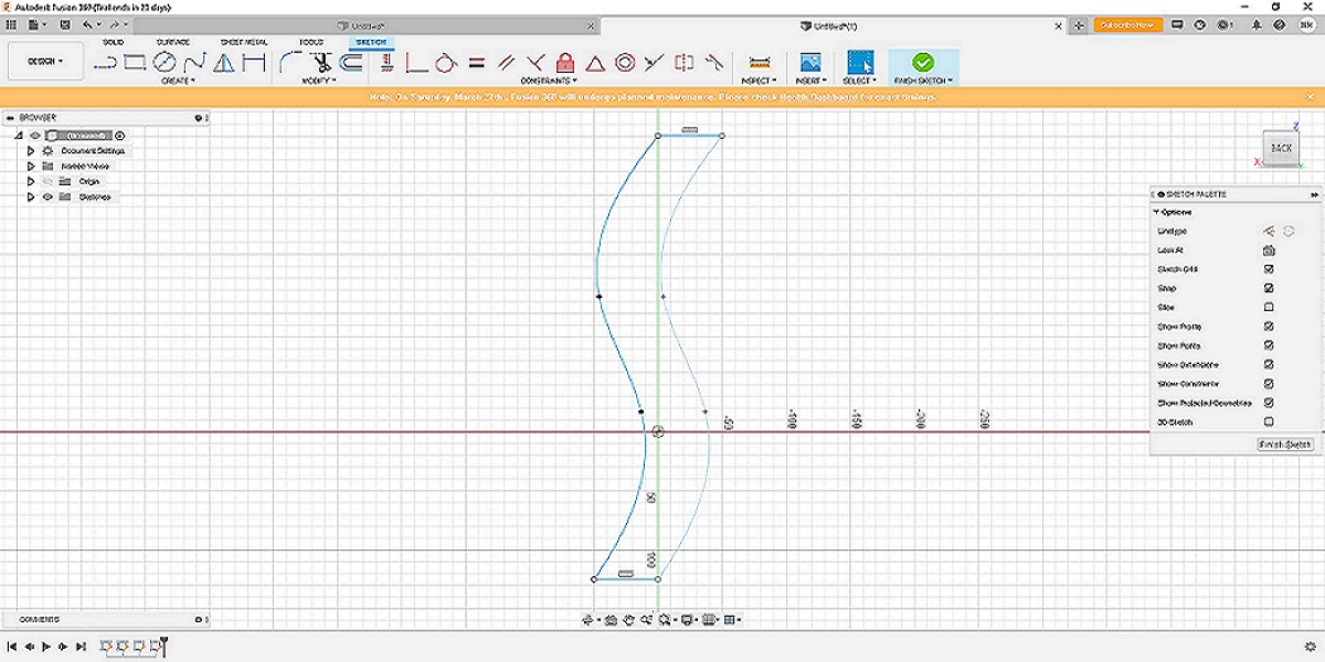
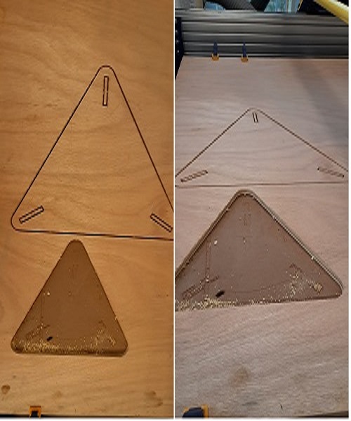
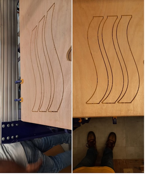
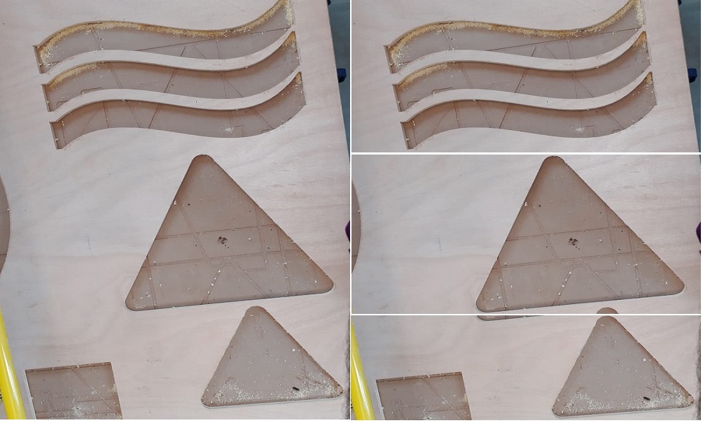
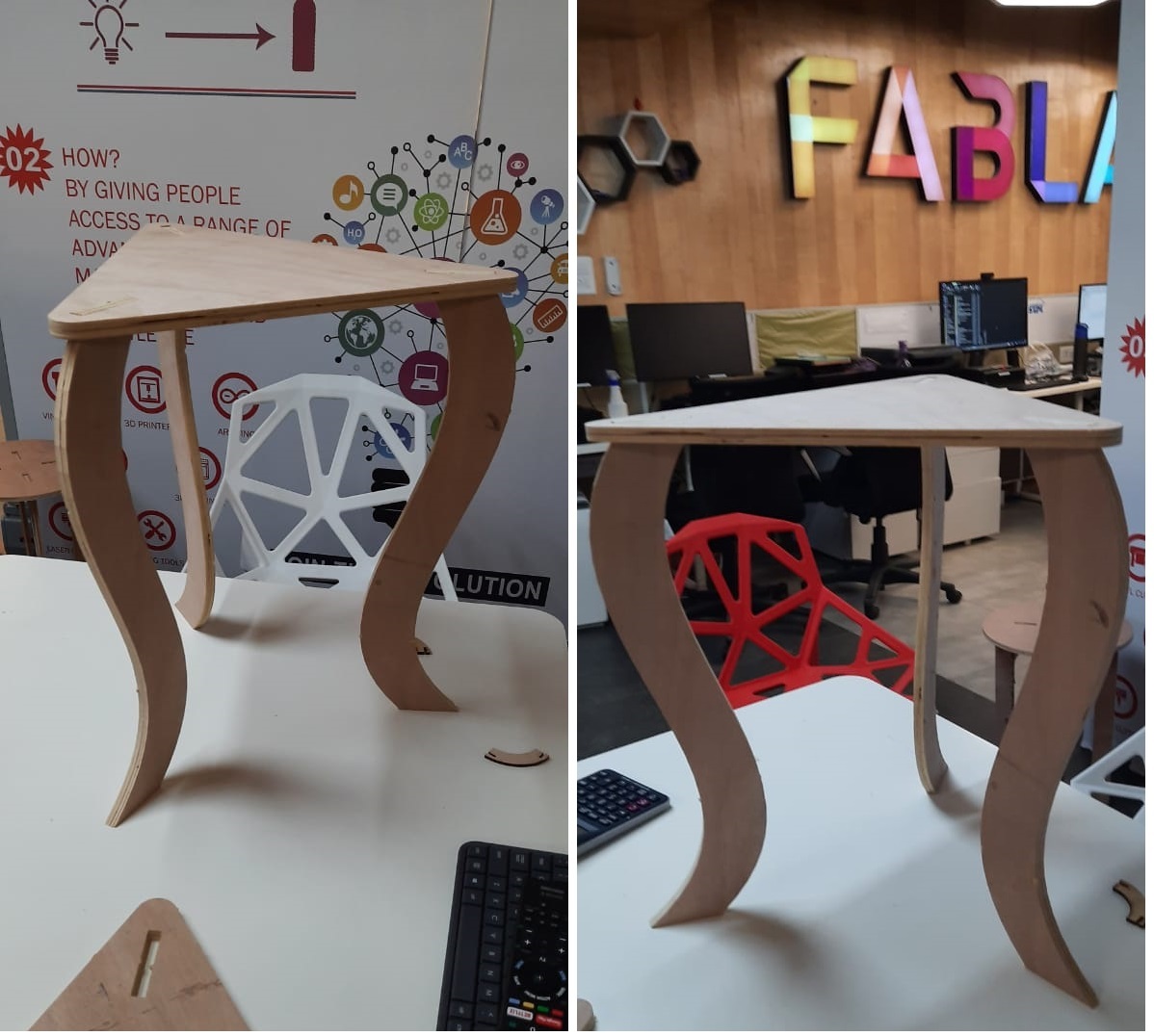
Since the assignment is all about make something big, I decided to make designed table with a triangular Top with 3 nos. of designed legs. I draw rough sketch of designed table on paper with dimensions. Skteching on the paper is very useful and important for designing. There are very few parts i.e. 3 foots, seat plate and supporting material like leg. I used 12mm plywood for this. I started with designing parts in solidworks & Fusion 360, First I designed foot part of bench has width, height.
| File Formats:: |
|
|
2D Design
a.Svg
b. DXF |
3D Design
a. STL
b. OBJ
|
|
|
| |
| Up Cut vs. Down Cut Router Bits |
| |
Up Cut Bits- Up cut bits are very efficient at evacuating chips from the hole or slot it is cutting. When the router is oriented with the bit up, as when mounted on a router table, the side of the bit closest to the operator is turning counter clockwise (left to right) and the back side clockwise (right to left).
Down Cut Bits- The downward slicing action of a down cut bit leaves a very clean, crisp edge around the hole or groove it cuts. While chips still are evacuated from the hole, a down cut bit is far less efficient in this respect than is an up cut design. The bit rotation is clockwise. The side of the bit farthest from the operator is turning counter clockwise (left to right) , the near side clockwise (right to left). This is very important for feed direction, as you always want the cutting edges turning against the feed direction, not with it. |
|
|
| The Difference |
|
|
| |
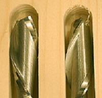
Though the flutes run in opposite directions, telling an up cut from a down cut bit can be difficult if you cannot imagine their rotation in the router. Though a router always turns in the same direction, from the operators perspective, that rotation appears to reverse depending on if the router is bit down in the common hand-held mode or bit up, as when mounted in a router table.
With the bit down, the rotation is clockwise. That means the side of the bit farthest from the operator is turning left to right, the near side right to left. This is very important for feed direction, as we always want the cutting edges turning against the feed direction, not with it. |
|
|
| |
|
|
|
 |
When the router is oriented with the bit up, as when mounted in a router table, the side of the bit closest to the operator is turning left to right and the back side right to left. Because the wood is fed against the rotation of the cutting edges, we almost always work against the front side of the bit.
If the wood is fed into a router bit on the wrong side, the feed direction matches the bits rotation, making a dangerous kick out all but certain. Feeding the wood with rather than against bit rotation allows the cutting edges to become highly efficient feed dogs that grab the wood, accelerate it and shoot it off the table at dangerous speeds. |
|
|
| (The down cut bit (left) leaves very clean edges while the up cut version (right) is far better at evacuating chips but that action can fray the edges of the cut to some degree.) |
|
|
| |
|
|
|
| Up Cut Bits |
|
|
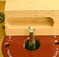 |
Up cut bits are very efficient at evacuating chips from the hole or slot it is cutting. This is especially important when the hole is ¼"-deep or more. Deep holes or grooves still have to be cut using multiple light cuts, but the upward direction of the flutes while rotating prevent the debris from building up in the hole and binding or even breaking the bit.
The problem with up cut bits is that the same action of the flutes that brings the chips up can also lift or fray the wood fibers around the edges of the cut. While this damage is usually minor, especially with good quality bits, it can be noticeable if those edges will be visible when the project is assembled.
Up cut bits are frequently used for cutting mortises because of their depth. Since the edges of a mortise are eventually hidden by the shoulders of the tenon that will be fit to it, this chipping or fraying will be hidden after assembly and have no impact on the finished project. |
|
|
This up cut bit is great for deep mortises because of how well it evacuates the chips. The minor fraying of the edges is of little concern because they will be hidden by the tenon shoulders when the project is assembled. |
|
|
| |
|
|
|
| Down Cut Bits |
|
|
|
 |
The down-ward slicing action of a down cut bit leaves a very clean, crisp edge around the hole or groove it cuts. While chips still are evacuated from the hole, a down cut bit is far less efficient in this respect than is an up cut design.
Down cut spiral bits are a good choice for cutting dados or shallow grooves, especially when the edges will be visible when the project is assembled. |
|
|
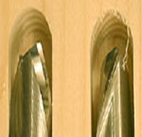
| Take a close look at the grooves cut by the down cut (left) and up cut (right) shows the marked difference in the edges they produce. |
|
|
| |
|
|
|
| |
Down cut bits require a slightly slower feed rate. This reduced pace allows the bit a little more time to throw chips out and for them to be re cut into smaller pieces that eventually are thrown from the hole or slot.The combination of a deep cut and a build up of chips can cause the bit to over heat and even break.
For most woodworkers, the down cut type of spiral bit is most useful, particularly for those using a router to cut dados, rabbets and visible slots. Some woodworkers like cutting mortises with a router, table mounted or hand-held. For them, the up cut bit will be most efficient. The ideal situation is to have both types of spiral bits in the drawer, in the size or sizes you most often use. The quest for more tools certainly does not end with spiral router bits. Up and down cut spiral bits are available in sizes ranging from ¼" to ½." We used bits from Infinity Tools for this story, both ½"-diameter. The Infinity part numbers are, up cut bit – 85-913, the down cut bit – 85-914.
|
|
|
| |
|
|
|
| |
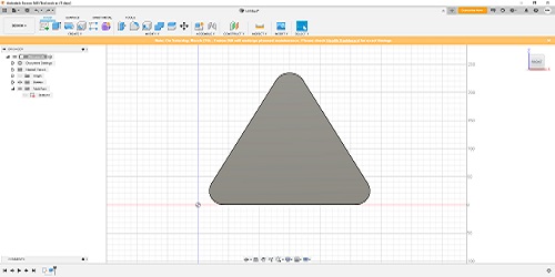
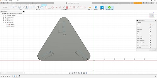
Intially, I found it a bit challenging to understand it first,as i have never been into this and this was my first time as I do not have any prior experience with designing softwares. Step by step i found it interesting and followed the instructions of our instructor's suggestion. He briefed us on how to design it first in 2D software and to convert it into 3D view along with various steps. |
|
|
| |
|
|
|
| To Start with the design and Procedures to be followed from Design to CNC |
|
|
Step-1 |
These are the steps to be followed to mill a design
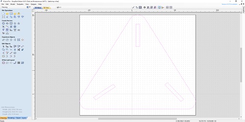
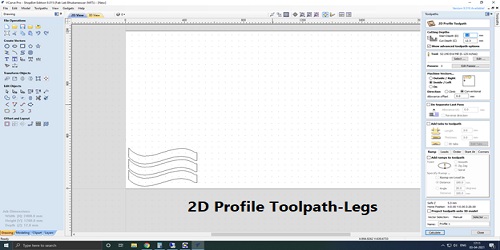
1.Make a 2d Drawing of the design you want to make
-Consider the tolerance
-Put the drawing into layers as per the cutting scheme
-Arrange the pieces to minimize the wastage ofthe material
-Leave ample distance between pieces to avoid overlap |
|
|
|
|
|
|
Step-2 |
Export it in .dxf format |
|
|
|
|
|
|
Step-3 |
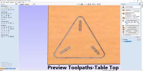
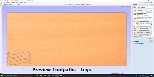
Import it into software that creates tool path (Fusion 360, Vcarve, Pathworks etc.)
-Choose the type of output i,e. cutting, pocketing etc)
-Choose the orientation of the bit
-Check all parameter
-See the preview in 3D |
|
|
| |
|
|
|
Step-4 |
Export it as .GCODE |
|
|
| |
|
|
|
Step-5 |
Milling machine
-Mount the correct drill bit
-Turn on the machine & the exhaust
|
|
|
| |
|
|
|
Step-6 |
Import GCODE into Shopbot |
|
|
| |
|
|
|
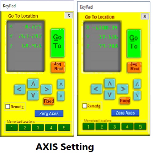
Step-7 |
Set your X, Y & Z as zero i,e. Origin |
|
|
| |
|
|
|
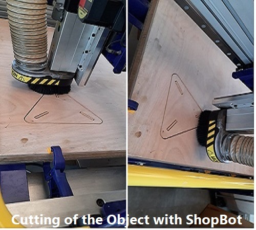
Step-7 |
Start the milling process of your design |
|
|
|